What are CAD files and how do you use them?
Although construction companies, architects, and engineers are moving more towards using BIM, they still use CAD files when designing. CAD files offer us (as specifiers and designers) a simple way to put together 2D plans and understand dimensions and layouts of a room and indeed an entire building.
So, what are they and how do you use them when planning healthcare facilities?
What is CAD?
Standing for Computer-Aided Design, CAD software can be used by architects, engineers, specifiers and all sorts of other designers to create precise illustrations and drawings for new buildings, refurbishments, or any other work that needs such planning.
You can use CAD software to create 2D drawings or 3D models.
Does Innova use CAD files? Can I download them?
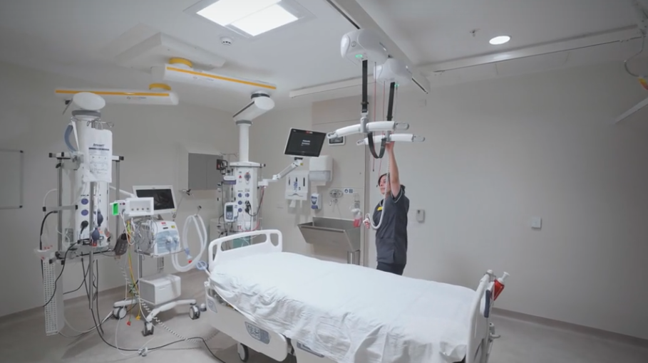
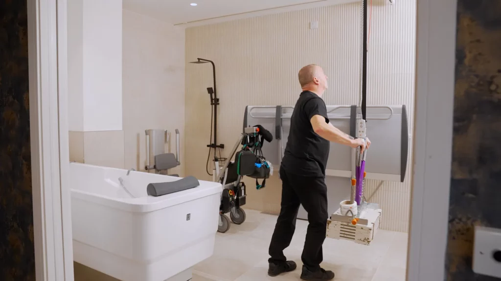
We certainly do use CAD files along with BIM files regularly. We have CAD files for our hoist systems, hoist units, bath layouts, Integralifts and much more.
These are all available to download for free once you’ve registered on our website. You can see a full list of our CAD files available to download here.
If you can’t find what you’re looking for, then please get in touch with our team. We regularly draw up bespoke CAD solutions and would be happy to help.
How do you use hoist CAD files?
HELPFUL HINT: The above shows the palette from which you can copy and paste the relevant track layout, radiuses, hoist, and coupling information if and as required. This palette will give you all the component parts to layout the track in plan view 2D format. You can download the components from the palette on our website.
The above shows a standard track layout with a 90° radius returning to the wall where the charge point (CP) is located. The track distance from the wall over a bed is usually a fixed distance of 1050mm due to the fact this is the optimum point of pick up for most patients with a sling/harness.
Start by laying out the centre line of the track (shown Magenta) and bring the components in from the palette snapping to the centre line. The radius can be snapped to one of the axes and then the other to locate correctly.
The Extend and Trim tools can then be used to either extend the track to meet the radius or snip shorter if the track is too long. Finally, add the fixings at correct distances depending on the weight loading (a radius requires 3 fixings), hoist and charge point. Layout complete!
Other things to think about when laying out hoists in CAD
With X-Y or H frames systems with a moving traverse rail, there is a need to observe minimum distances from walls for both track and transit couplings.
The fixed track is usually installed 250mm parallel away from walls, leaving an overhang of the traverse rail of 200mm. Check for any floor to ceiling furniture or IPS panels which may conflict, and it might be necessary to shorten the traverse rail or move a fixed rail accordingly.
When a transit coupling is installed, the distance from the doorway to the centre of the track should be 600mm to allow for all clearances.
The number of fixings for the fixed track is important depending on the weight limit of the hoist which is to be used.
- Every length track has to have a minimum of 3 ceiling fixings regardless of whether or not there are wall support brackets in use (and whether or not these are fastened to a structural wall).
- Wall support brackets are not designed to support a load but just prevent lateral movement. The distance between a wall support bracket and a T mount should be no more than 100mm if the wall is not masonry, and 1000mm if the wall is masonry.
- For a 200kg hoist unit, T mounts should be installed every 2m plus 1 fixing at either end of the track.
- For a 260kg hoist unit, T mounts should be installed every 1.5m plus 1 fixing at either end of the track.
- For a 350kg hoist unit, T mounts should be installed every 1m plus 1 fixing at either end of the track.
- For a 500kg hoist, unit T mounts should be installed every 500mm plus 1 fixing at either end of the track.
The best way of calculating the number of fixings is to take a measurement between the 2 outer fixings (the ones which are fixed 100mm from the wall), then divide the distance to ensure fixings are within the spacing requirement for the anticipated weight load.
For example, in the diagram below the measurement between the 2 outer fixings is 4600mm. Let’s assume a hoist capacity is 200kg so there should be a fixing every 2 metres (maximum).
Using only 1 fixing would equate to a 2300mm span which is not satisfactory. Here we’ve used 2 fixings evenly spaced would equate to 1533mm which is well within our limit, so 2 fixings will be inserted (total of 4 for the complete track) as shown below.
Spacing the fixings evenly also is better from an aesthetics point of view if the fixings are visible.
Can you overlay Innova CAD files on top of other layouts?
This would only happen with a large-scale project such as a hospital where the rooms follow the same pattern in relation to size and layout. It is then possible to create the room system as a block and paste this into the room space which does save a lot of time.
However, most room sizes are different and need a bespoke system or the editing of a standard layout.
I hope that this blog post has covered any queries you may have had about CAD files and how they are used in healthcare layouts. Our design team work in both CAD and BIM every day, so please get in touch if you have any question.
Don’t forget that all our CAD files are available to download from our website, and we can also help if you can’t find the exact design you’re looking for!
Autodesk, AutoCAD, DWG, the DWG logo, and Inventor are registered trademarks or trademarks of Autodesk, Inc., and/or its subsidiaries and/or affiliates in the USA and other countries.